WiFi Module SCF-12F
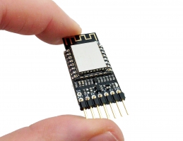
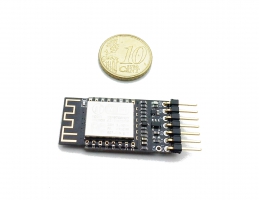
We chose to use a WiFi hardware already widely employed on the market (the ESP-12F) on which we uploaded our innovative µPanel firmware. To highlight the fact the module firmware has been completely changed with respect to other commercial products, we chose to name it SCF-12F.
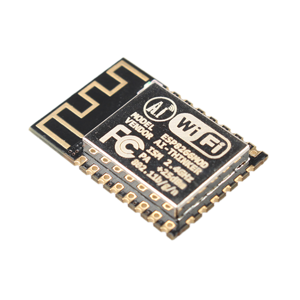
All the functions of the WiFi Module are managed by the powerful system on chip (SoC) ESP8266, that combines a 32 bit micro-controller (and many peripherals, such as GPIO, I2C, ADC, SPI, PWM) with a WiFi radio.
Pins of the SCF-12E module
| RST | External reset signal, active low | MOSI * | MOSI for SPI interface | |
| ADC * |
10-bit ADC Analog Input 0-1V | SCLK * | Serial Clock for SPI interface | |
| CHIP-EN | Chip Enable, active high | GND | Power Ground | |
| GPIO16 | General Purpose I/O | GPIO15 | General Purpose I/O | |
| GPIO12 | General Purpose I/O | GPIO2 | General Purpose I/O (connected to the LED) | |
| GPIO13 | General Purpose I/O | GPIO0 | General Purpose I/O | |
| VCC | +3.3V power input | GPIO4 | General Purpose I/O | |
| CS0 * |
Chip Select for SPI interface | GPIO5 | General Purpose I/O | |
| MISO * |
MISO for SPI interface | RX | UART RX | |
| GPIO9 |
General Purpose I/O (only on 12-D version) | TX | UART TX | |
| GPIO10 | General Purpose I/O (only on 12-D version) |
* Not managed from miuPanel firmware.
Leds Module
| Blue LED |
(GPIO2) | Connected to GPIO2 |
Operating mode
After power-up (or reset) the module can boot in two different modes, depending on the logic levels applied on pins GPIO0 and GPIO2 and GPIO15:
Electrical specification
This module requires 3.3 V on VCC and 3.3 V for the logic. It does NOT tolerate 5 V!
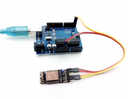
If you use Arduino UNO, and you connect to the Wi-Fi module the RX and TX pins of Arduino, you will destroy the module.
Moreover, the 3.3 V source of Arduino Uno has inadequate current capability to power this module. You should use a separate 3.3 V source to power the module, with a current capability of 300 mA or higher, because the average current consumption of the Wi-Fi module is about 100 mA.
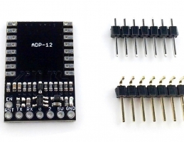
To simplify the connection of the our Wi-Fi module with a 5 V board (like Arduino), we designed the ADP-12 Breadboard adapter.


