Remotely Control a Relay with Arduino UNO
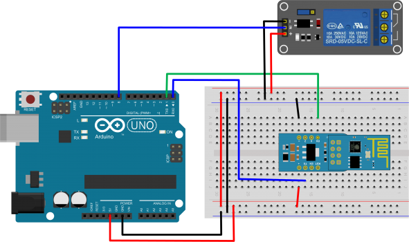
This section presents a simple example that shows how to remotely control through Internet a Relay connected to an Arduino Uno board with µPanel.
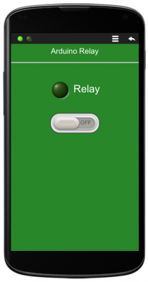
This example uses the same panel presented in the Basic Examples, which consists in a Switch and a LED indicator. Arduino will be waiting for the user to change the switch state and will update the Relay and the LED status accordingly.
Hardware
- Arduino UNO Board
- ESP-01 WiFi module (with µPanel Firmware)
- ADP-01 Breadboard adapter
- Breadboard
- Relay Board

Please note that for programming Arduino Uno, the RxD line (blue wire) has to be disconnected from the WiFi Module
µPanel definition
The panel definition includes a text for the panel title, a standard green LED and an On/Off default switch.
D!282;T*15:Arduino Relay;=*20/L1G:0:Relay;/*10W1:0;

Arduino Code
void setup() {

  // Initialize Serial Port
  Serial.begin(57600);

  // Let uPanel start
  delay(3000);

  // Discharge old partial messages
  Serial.println("");

  // Send The Panel (A LED and a Switch)
  Serial.println("$P:D!282;T*15:Arduino Relay;=*20/L1G:0:Relay;/+*10W1:0;");

  // Initialize digital output pin
  digitalWrite(8, 1);
  pinMode(8,OUTPUT);

}

String Msg;

void loop() {

  int c;
  while ((c = Serial.read()) > '\n') Msg += (char) c;  // Read incoming chars, if any, until new line
  if (c == '\n')                                       // is the message complete?
  {
    if (Msg.equals("#W10")) {digitalWrite(8,1); Serial.println("#L10");}    // Turn OFF LED 1 and Relay if switch is OFF
    if (Msg.equals("#W11")) {digitalWrite(8,0); Serial.println("#L11");}    // Turn ON LED 1 and Relay if switch is ON
    Msg = "";
  }

}
Control Two Relays
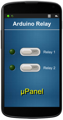
We can easily modify the previous example in order to control two relays. To do that, we have just to connect another Arduino’s digital output to a second Relay and change a few lines of code:
- we change the panel definition in order to add the second control channel and to make the panel nicer:
D!g11;/5T*25fb:Arduino Relay;=*16/30{mL1G:0;|*12W1:0;|T:Relay 1;}/{mL2G:0;|*12W2:0;|T:Relay 2;}/30*20T#FF0ht3,000:μPanel;

Serial.println("$P:Dg11;/5T*25fb:Arduino Relay;=*16/30{mL1G:0;|*12W1:0;|T:Relay 1;}/{mL2G:0;|*12W2:0;|T:Relay 2;}/30*20T#FF0ht3,000:μ");
we add four lines of code in order to manage the second switch:
  ...
  digitalWrite(9, 1);
  pinMode(9,OUTPUT);
  ...
  if (Msg.equals("#W20")) {digitalWrite(9,1); Serial.println("#L20");}    // Turn OFF LED 2 and Relay if switch is OFF
  if (Msg.equals("#W21")) {digitalWrite(9,0); Serial.println("#L21");}    // Turn ON LED 2 and Relay if switch is ON
  ...
Watch the video of this example:

