Control of a RGB LED Strip with Arduino UNO
Control of a RGB LED Strip with Arduino UNO
In this example, we remotely control a RGB LED strip.

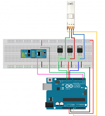
LED strips can be easily controlled with any kind of microcontroller. In this example, we use PWM dimming techniques to control the power for each RGB channel of the strip. Since each color channel may absorb a lot of current (of the order of few Amps, or more), power transistors are required! Don’t try to connect the channels of the strip LED directly to your microcontroller, they will damage the microcontroller outputs or not work.
You can use any power NPN BJT or N-Channel MOSFET, but make sure the transistor is rated to be able to manage as much current as you need. For example, if your LED strip draws 0.2 A/m per channel, if you have a 5 m strip you will need up to 1 A transistor. The common package for power transistor is the TO-220.
For basic, low-cost systems we suggest using N-channel MOSFET such as the IRF520N or the ST P55NF06 or the TIP120, they are very popular and inexpensive. If you can’t get those, the NPN transistors are also good, but they have higher power losses than in MOSFETs, which is why we suggest those first.
Hardware
- Arduino UNO Board
- ESP-01 WiFi module (with µPanel Firmware)
- ADP-01 Breadboard adapter
- Breadboard
- RGB LED Strip
- Power transistors (we used the N-MOS STP55NF06)

For longer strips requiring more than 1A, wire the external power source cable directly to the strip, then connect power and ground wires back to the Arduino.
In case you use a NPN transistor, remember to add a 100-220 ohm resistor between the microcontroller PWM outputs and the base pin of transistors.
µPanel definition
To show the flexibility of the miuPanel graphics, we have reproduced a simple infrared controller, usually supplied with the RGB strip.
Using the Online Panel Simulator you can easily design and check the panel layout before loading it on Arduino.
/10*10fb{-5%90,y90r30!FFF,DDD^|/5T#000:RGB LED Controller;/10
{{%45,20r20^!888B1%36,36r80!FFF:+;|B2%36,36r80!FFF:-;}|{%45,20r20^!888B3%36,36r80!F00:Off;|B4%36,36r80!0F0:On;}}_
{%90,y60r20^m!888BA%18,18r80!F00:R;|BB%18,18r80!0F0:G;|BC%18,18r80!00F:B;|BD%18,18r80!FFF:W;_
BE%18,18r80!F60:;|BF%18,18r80!FC0:;|BG%18,18r80!FF0:;|BH%18,18r80!C60:;_
BI%18,18r80!3F9:;|BL%18,18r80!6FF:;|BM%18,18r80!3CC:;|BN%18,18r80!069;_
BO%18,18r80!F0C:;|BP%18,18r80!F6C:;|BQ%18,18r80!F9F:;|BR%18,18r80!906:;}}
As you can see, we used 20 buttons. For each button we used some styles to specify the dimension (style “%”), the shape (style “r” to roud the corners) and the background (style “!”) ad so on.


Arduino Code
Please note that for programming Arduino Uno, the RxD line (blue wire) has to be disconnected from the WiFi Module.
void setup() {

  #define BLUEPIN   9
  #define REDPIN  10
  #define GREENPIN  11

  // Initialize Serial Port
  Serial.begin(57600);

  // Let uPanel start
  delay(3000);

  // Discharge old partial messages
  Serial.println("");

  // Send The Panel (split in different messages for convenience, not mandatory)
  Serial.print  ("$P:/10*10fb{-5%90,y90r30!FFF,DDD^|/5T#000:RGB LED Controller;/10{{%45,20r20^!888B1%36,36r80!FFF:+;");
  Serial.print  ("|B2%36,36r80!FFF:-;}|{%45,20r20^!888B3%36,36r80!F00:Off;|B4%36,36r80!0F0:On;}}_{%90,y60r20^m!888");
  Serial.print  ("BA%18,18r80!F00:R;|BB%18,18r80!0F0:G;|BC%18,18r80!00F:B;|BD%18,18r80!FFF:W;_");
  Serial.print  ("BE%18,18r80!F60:;|BF%18,18r80!FC0:;|BG%18,18r80!FF0:;|BH%18,18r80!C60:;_");
  Serial.print  ("BI%18,18r80!3F9:;|BL%18,18r80!6FF:;|BM%18,18r80!3CC:;|BN%18,18r80!069;_");
  Serial.println("BO%18,18r80!F0C:;|BP%18,18r80!F6C:;|BQ%18,18r80!F9F:;|BR%18,18r80!906:;}}");

  // Settings I/O
  pinMode(REDPIN, OUTPUT);
  pinMode(GREENPIN, OUTPUT);
  pinMode(BLUEPIN, OUTPUT);
}
String Msg;
unsigned char state = 0;

unsigned char brightness; // (0-10)
unsigned char red = 0;    // red level 0-25 (referred to lowest brightness step)
unsigned char green = 0;  // green level 0-25 (referred lowest brightness step)
unsigned char blue = 0;   // blue level 0-25 (referred to lowest brightness step)
unsigned char red_b;      // red level 0-255 (referred to selected brightness)
unsigned char green_b;    // green level 0-255 (referred to selected brightness)
unsigned char blue_b;     // blue level 0-255 (referred to selected brightness)
char button_id;

void loop() {

  int c;

  while ((c = Serial.read()) > '\n') Msg += (char) c;  // Read incoming chars, if any, until new line
  if (c == '\n')                                       // is the message complete?
  {
    if (Msg.substring(0,2).equals("#B")){  // a button is pressed
      button_id = Msg.charAt(2);

      switch (button_id){

        case '1':  // Increase brightness
          if (brightness <10)
            brightness++;
          break;

        case '2': // Decrease  brightness
          if (brightness >1)
            brightness--;
          break;

        case '3':  // Switch OFF
          digitalWrite(8, 0);
          red = 0;
          green = 0;
          blue = 0;
          state = 10;  // switch off requested
          break;

        case '4':  // Switch ON
          if(!state){
            digitalWrite(8, 1);
            red = 0;
            green = 25;
            blue = 0;
            brightness = 3;
            state = 1;
          }
          break;

        case 'A':
          red = 25;
          green = 0;
          blue = 0;
          break;

        case 'B':
          red = 0;
          green = 25;
          blue = 0;
          break;

        case 'C':
          red = 0;
          green = 0;
          blue = 25;
          break;

        case 'D':
          red = 25;
          green = 15;
          blue = 25;
          break;

        case 'E':
          red = 24;
          green = 10;
          blue = 0;
          break;

         case 'F':
            red = 24;
            green = 19;
            blue = 0;
          break;

        case 'G':
          red = 19;
          green = 10;
          blue = 0;
          break;

        case 'H':
          red = 25;
          green = 5;
          blue = 5;
          break;

        case 'I':
          red = 5;
          green = 24;
          blue = 14;
          break;

        case 'L':
          red = 10;
          green = 24;
          blue = 24;
          break;

        case 'M':
          red = 5;
          green = 19;
          blue = 19;
          break;

        case 'N':
          red = 0;
          green = 10;
          blue = 14;
          break;

         case 'O':
          red = 20;
          green = 0;
          blue = 25;
          break;

        case 'P':
          red = 20;
          green = 5;
          blue = 20;
          break;

        case 'Q':
          red = 25;
          green = 10;
          blue = 25;
          break;

        case 'R':
          red = 20;
          green = 0;
          blue = 10;
          break;
        }
      }

    Msg = "";  //clear string

    if (state > 0 ){  // Update the outputs

      red_b = red * brightness;
      green_b = green *brightness;
      blue_b = blue * brightness;

      analogWrite(REDPIN, red_b);
      analogWrite(GREENPIN, green_b);
      analogWrite(BLUEPIN, blue_b);

      if(state == 10)  // requested off
        state = 0;
    }
  }
}
Watch the video of this example:

